
How to Choose a Modular Blister Seal Machine for Preformed Blisters
Trapped Blister Packaging With Folded or Two-Piece Cards
Respuesta rápida: Trapped blister packaging holds a formed plastic blister by capturing its flange between front and rear layers of paperboard. Those layers can come from one folded card or two separate cards joined around the blister.[1][2] Choosing between them starts with the window, flange and card layout, followed by a sample check of assembly and sealing.
1. The Card–Flange Cross-Section

Start at the front of the pack. The plastic cavity projects through a die-cut window in the front card. Around the base of that cavity, the plastic extends outward to form a flange. The front card overlaps this flange, while the rear card sits behind it. Joining the card layers closes the structure and holds the flange between them.[2]
Two areas deserve separate attention on the drawing:
- Flange retention area: where the front card overlaps the plastic flange and helps keep the blister from passing through the window.
- Card-to-card joining area: where the two paperboard layers meet and are joined. In the illustrated arrangement, this area lies outside the flange.
This distinction matters when reviewing a sample. A large card border does not, by itself, establish that the flange is captured correctly or that the joining area has adequate support. Check both relationships on the actual materials.
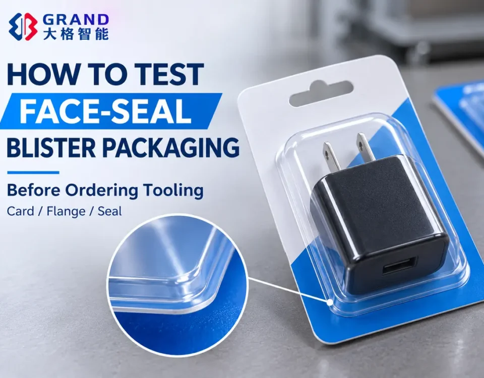
For the design Macpac describes, the plastic is held between the cards without being sealed directly to the paperboard.[1] A face-seal pack instead attaches the blister flange to a single backing card. If that is the structure in your sample, use the guide to testing a face-seal blister sample. The broader tipos de envases tipo blíster guide covers the other common formats.
2. Folded and Two-Piece Cards
A fold-over card forms the front and rear layers from one connected blank. A two-piece blister card uses a separate front and back. Both can create a trapped blister, provided the window and joined layers retain the flange. A folded card can also serve as a cover without creating this structure, so judge the assembled pack rather than the card name alone.[2]
The layouts below show the card pieces before assembly; the fold-over option keeps the two panels connected.

Table 1. Folded and Two-Piece Blister Cards
| Review point | One fold-over card | Two separate cards |
|---|---|---|
| Front and rear layers | Identify both panels and the connecting fold on one blank. | Identify the front and rear as separate components. |
| Alignment | Check the fold line against the window, cavity and printed artwork. | Check the locating references and orientation of both cards. |
| Drawing and material records | Mark panel orientation, joining faces and material on the unfolded drawing. | Record each card’s drawing revision, material and joining face. |
| Feeding and assembly | Confirm whether the card arrives flat, precreased or prefolded, and where folding occurs. | Confirm the loading order, locating method and missing-card checks. |
| Sample decision | Examine fold quality, closure and flange retention using the proposed stock. | Examine front-to-back registration, closure and flange retention using both proposed stocks. |
On a smaller screen, scroll the table horizontally to read all columns.
Choose from the assembly trial
For a folded card, inspect the complete closing movement. Check whether the window edge catches the cavity, whether the crease draws either panel away from its intended position, and whether the layers meet without forcing the blister sideways. A connected blank still needs a repeatable folding and locating method. Use the proposed card stock and a formed blister; a thin paper mock-up is useful for layout discussion but does not establish the behavior of the finished materials.
For two separate cards, identify the front and rear, their joining faces and their loading orientation. Watch each placement and check whether the first component moves as the next is added. Include a simple way to distinguish card versions during the trial, particularly where several products share similar artwork.
If the folded sample loses alignment during closure, review the crease, panel layout and locating method before rejecting the format. If the separate cards are difficult to orient consistently, review their locating references and the assembly sequence. Neither observation alone proves that the other format will work better.
When both options meet the same retention, appearance and opening requirements, compare the demonstrated loading steps, replenishment and changeover work. Include any requirement to revise the front and rear artwork independently. Base the choice on the complete pack and assembly trial; the number of card pieces alone does not establish cost or production speed.
3. Window, Flange and Seal Area
Use the following review sequence to turn the card dieline and blister drawing into one coordinated layout. The checks are a practical discussion framework; dimensions and acceptance limits must come from the agreed project specification.
Start with matching drawings and locating references
Confirm the drawing revision, units and scale for the card and formed blister. Show the folded blank in both its open and closed positions, or identify the two separate cards individually. Align the drawings from the edges, holes or other features intended to locate the parts during assembly. Centering them by eye can conceal a mismatch between the design and the proposed fixture.
Mark four outlines separately: the cavity, the front-card window, the outside of the plastic flange and the card-to-card joining zone. Include the card perimeter, fold and hang hole so that local changes can be checked against the rest of the pack.
Review clearance and flange capture together
Check that the cavity passes through the opening without unintended contact. Pay attention to corners, narrow necks and changes in cavity shape. Then mark the portion of the flange covered by the front card. Enlarging the window to resolve contact also changes this coverage, so review both relationships whenever either outline changes.
Apply the manufacturing and assembly tolerances agreed for the actual components. Review the least favorable permitted positions, including movement toward a narrow edge or corner. Record where coverage becomes smallest and where the cavity approaches the window. A well-centered display sample is useful, but it cannot establish the result throughout the permitted variation.
The drawing overlay below holds the blister fixed while shifting the window to the right. It shows two changes together: less cavity clearance on the left and less flange coverage on the right.

Identify the joining faces and tooling support
Macpac describes a construction in which die-cut, creased cards are heat-sealed together around the blister flange.[3] Identify the joining method for your own pack, along with the card stock, coating or adhesive, and the faces that must meet. Mark the area supported by the sealing fixture separately from the flange-retention area. Review the local material stack wherever a fold or plastic edge approaches the joining zone.
Include hanging and opening in the same layout
Place the hang hole, tear feature and intended opening route on the coordinated drawing. Assemble the actual product in its intended orientation and observe how the pack hangs. During an opening check, note which part of the card is pulled or torn and where that action meets the retained flange or joined border. Agree the required opening behavior and acceptable visible damage before judging the result.
Save the annotated layout with the component revisions and the sample identifier. If the window, flange, card stock, crease or opening feature changes, mark the affected relationships for review in the next trial.
4. Reading the First Assembled Sample
Inspect the components in their intended locating fixture before joining, then compare that assembly with a matched joined sample. Record how the parts are supported during each check. Use the pre-joining inspection to assess fit and placement; evaluate final blister retention after joining. The observations below are starting points for investigation, not confirmed diagnoses.
Table 2. Sample Observations and Follow-Up Checks
| What you see | What to check | What to record |
|---|---|---|
| The blister moves more than expected inside the closed cards. | Compare the movement with the agreed retention requirement. Inspect flange coverage, cavity-to-window clearance and the position of both cards. | Movement direction and extent under the agreed check, the affected edge, and the component positions recorded before joining. |
| The window edge catches or rubs the cavity. | Compare the cut opening with the blister drawing. Observe the folding path, card orientation and how the blister sits in the fixture. | A marked contact location and the assembly step at which contact begins. |
| A drawing overlay or assembly inspection indicates less flange coverage than specified at one edge. | Check actual part dimensions and placement against the intended locating references. Review the agreed tolerance positions at that edge. | Component measurements, locating references and marked overlap on the coordinated drawing, with photographs where the flange is accessible. |
| A card lifts or the assembly bows after closure. | Compare unjoined and joined samples. Inspect the crease, local material stack and support beneath the joining area. | Where the gap or bow appears, whether it existed before joining, and the materials used. |
| The loaded pack hangs at an unwanted angle. | Check product orientation, cavity placement and hang-hole position together. Compare the result with the agreed display requirement. | The loaded hanging position, product identity and weight, plus any visible card distortion. |
On a smaller screen, scroll the table horizontally to read all columns.
For example, if the card joint passes its agreed check but the blister moves farther than the specified limit, record the direction and extent of movement and inspect the corresponding flange coverage and placement. Review geometry and positioning before proposing a process change. Joint performance and blister retention are separate acceptance items; verify both.
5. Samples and Sealing Compatibility
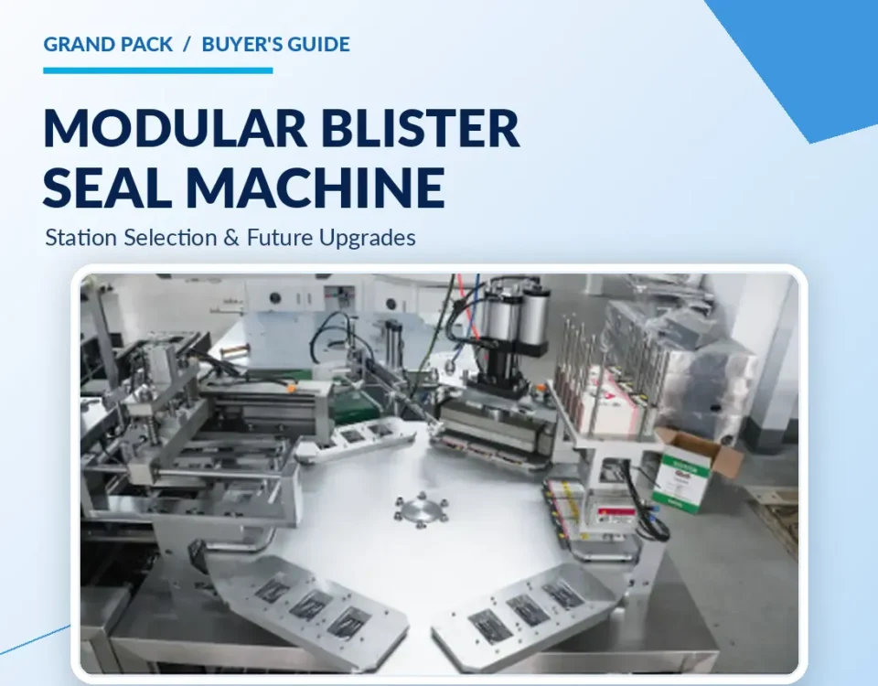
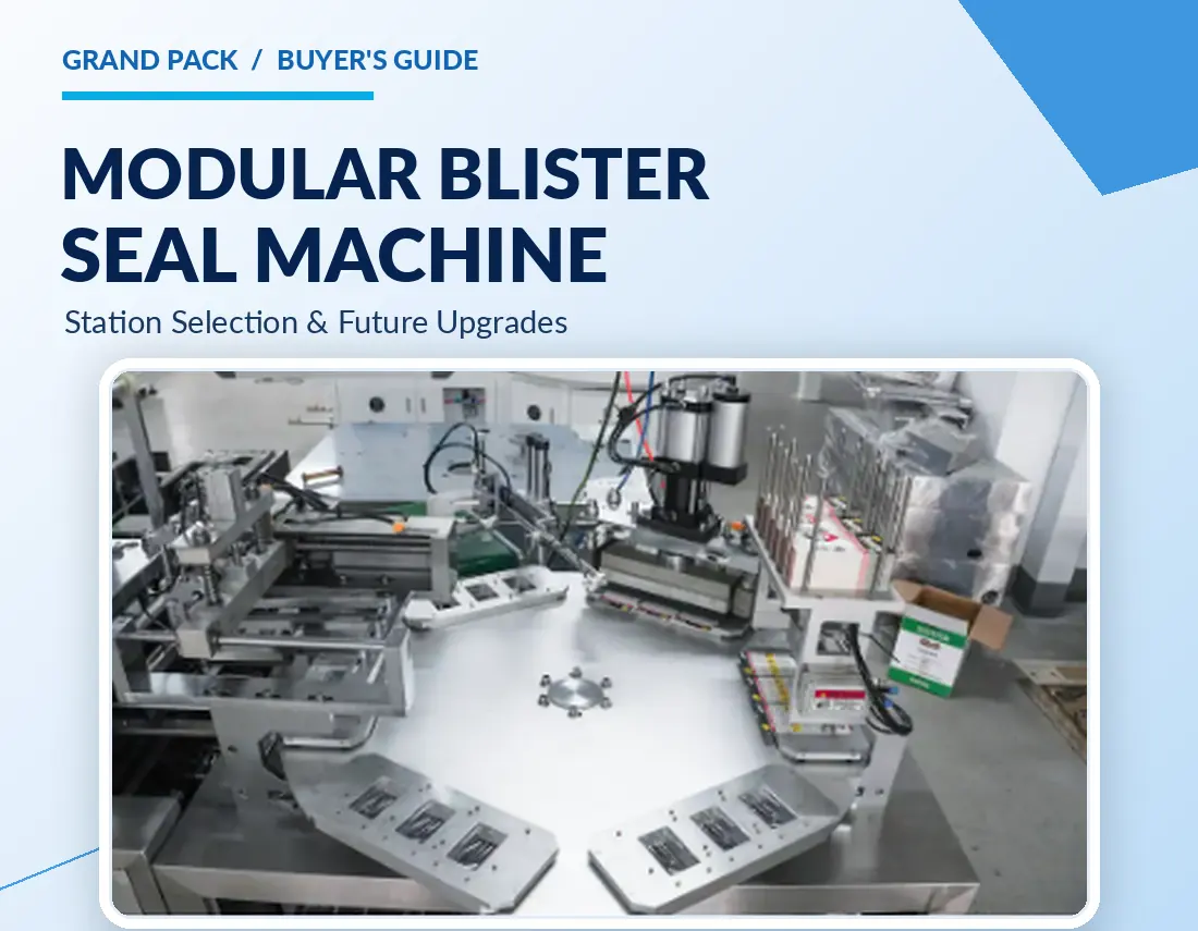
The equipment review should follow the proposed pack through loading, locating, joining and unloading. Use the actual cards and formed blisters so the trial includes their stiffness, folding behavior and fit in the fixture.
Demonstrate the agreed loading and locating sequence on the proposed tooling, including closure, and show how the pack remains supported until joining is complete.
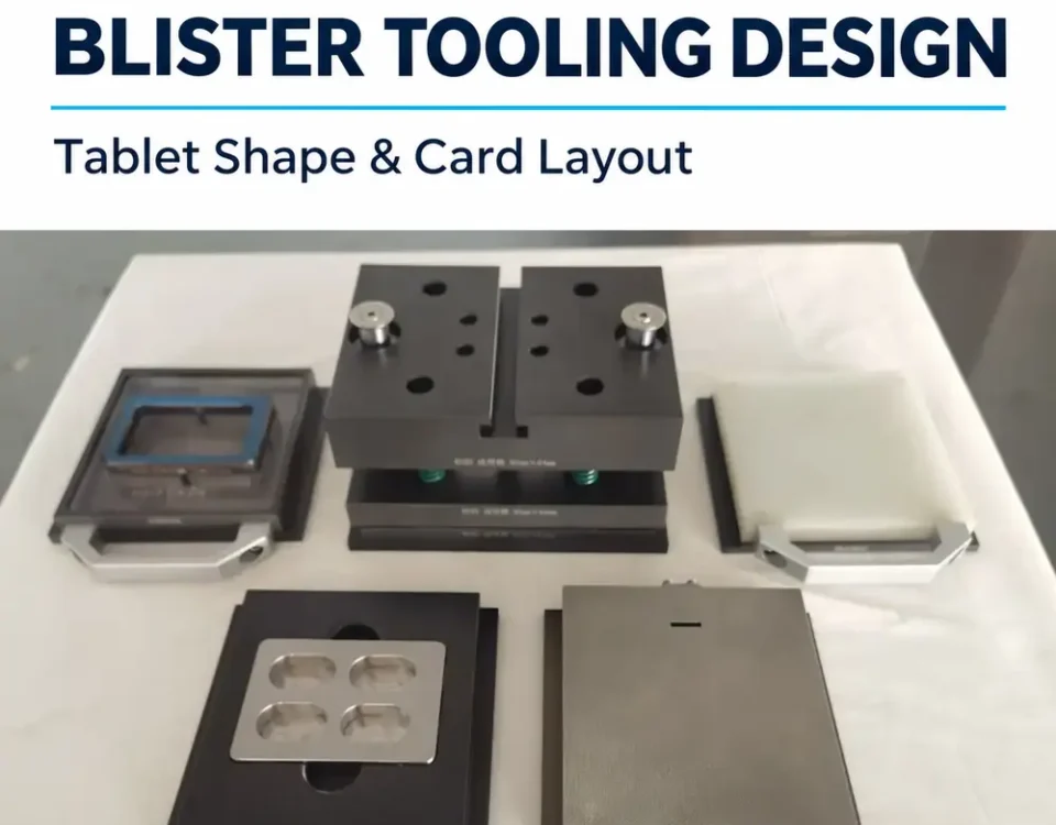
Then confirm how the tooling supports the joining area and accommodates the projecting cavity. Agree a trial plan covering the selected materials, recorded process settings and finished-pack checks. Link the results to the component and tooling revisions used; this provides a usable baseline when the design changes.
One documented industry example is HAMER’s HC 63, which its manufacturer lists for both single-card face-seal packaging and trapped blisters sealed between two cards.[4] That statement describes the HAMER model; compatibility of a proposed GRAND system should be established with the specific pack, feeding arrangement and tooling. For a fuller discussion of loading, sealing and discharge arrangements, see selecting blister sealing stations.
Prepare four groups of information for a useful sample review:
- Card layout and material: the unfolded drawing or both card drawings, showing windows, folds, joining faces and revisions, with matching card samples.
- Blister and flange details: the cavity and flange drawing, plastic specification and corresponding formed samples.
- The actual product: representative samples, dimensions and weight, including the intended orientation inside the cavity.
- Display and opening requirements: how the pack will be presented, how it should hang or stand, and how the customer should open it.
6. Record the Trial and Decide What to Change
Define the acceptance criteria before the trial. Separate card-joint condition, blister retention, appearance, display behavior and opening performance, and identify how each will be checked. Where handling or distribution requirements apply, include the agreed conditions in the trial plan. A visually tidy sample should not automatically be recorded as a pass.
Keep a short record that allows another reviewer to reconstruct the sample:
- Componentes: sample ID; front and rear card revisions or folded-blank revision; blister drawing revision; material specifications and batch identifiers where available.
- Assembly: product identity, weight and orientation; loading order; locating references; fixture or tooling revision; joining method and process settings used.
- Evidence: number of samples examined; annotated photographs and measured locations; method and conditions of each check, including hanging and opening; observation time or conditioning state after joining where relevant.
- Decision: result against each agreed criterion, unresolved questions, and the specific drawing, material or process item to review next.
Use three clear outcomes: accept the tested samples against the agreed trial criteria, revise and repeat the affected checks, or hold the decision until missing evidence is available. Record the reason alongside the outcome. For a revision, identify the intended correction and check that it has not compromised another relationship—for example, that a larger window still provides the required flange capture.
To discuss a blister-card packaging project with GRAND, send the coordinated drawings, matching samples and trial requirements together. Include existing observations if a sample has already been assembled. This gives the equipment review a defined pack and a clear set of questions about loading, locating, tooling support and joining.
Questions Before Sample Approval
What makes a trapped blister different from a face-seal blister?
A trapped blister retains its flange between front and rear card layers. A face-seal blister attaches its flange to one backing card. Check where the flange sits and which surfaces are joined; those details determine which sample checks and tooling questions apply.
Does a trapped blister need two separate cards?
Does the blister flange have to be sealed directly to the card?
Not in the construction described by Macpac, where the cards hold the blister without direct plastic-to-paperboard sealing.[1] Identify the intended card-to-card joining surfaces on your drawing and have the supplier confirm the construction for the proposed materials.
Can an existing blister sealer handle a trapped-card pack?
Ask its supplier to review the actual samples and tooling requirements. The review should cover both card layers, loading and locating, cavity clearance, support of the joining area and the selected sealing method. Use a trial to establish the finished-pack result.
How much of the blister flange should the front card cover?
Determine coverage from the actual window and flange geometry, the agreed manufacturing and assembly tolerances, and the required retention performance. Review narrow edges and corners in the least favorable permitted positions, then evaluate matching samples. A single overlap dimension cannot establish the behavior of the complete pack.
Why can the blister move even when the card is closed?
Closing the card layers does not establish that movement is within the agreed limit. Review flange coverage, window clearance and component placement. Use the assembly in its locating fixture to check fit before joining, and the joined sample to assess retention. Record the observations before deciding which layout, locating or joining condition needs further review.
Referencias
Discuss Your Blister Card Layout
Share your card layout, blister flange drawing, product weight and display requirements.